3rd Years Work
HOUSING
Title - Insieme
Instructor - Louis Molina
Location - Boyle Heights
Year - 2016
Typology - Tower
In lower Boyle Heights near the future project Ribbon of Light Bridge by Michael Maltzan. An industrial area with minimal housing. The project began by the precedent the Cherokee Lofts/ Studio located in Los Angeles.
CHEROKEE LOFTS
In analyzing the Cherokee Lofts, there were lots of different parts that composed the building and how individuals interacted with it. As a housing complex and commercial space, it has the public aspect at the bottom of the structure, facing towards the street. To keep the privacy of an apartment complex on the second level with its own secluded entrance.

LIGHT DIAGRAM
LAYOUT OF UNITS

MASS
THRESHOLDS
CIRCULATION

SUPPORT
STRUCTURE
PART TO WHOLE

DIAGRAM OF THE SURROUNDING AREA
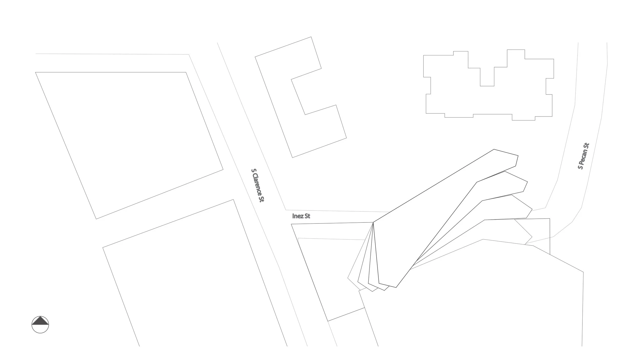
Through analyzing Boyle Height it was determined that the city grid compresses, especially when it came to housing. This left inhabitants without many parks near by, or spaces to gather with friends. In this diagram it shows how these public spaces are rare. How public spaces tend to be located away from residential areas, realizing the need for an open area to be developed.

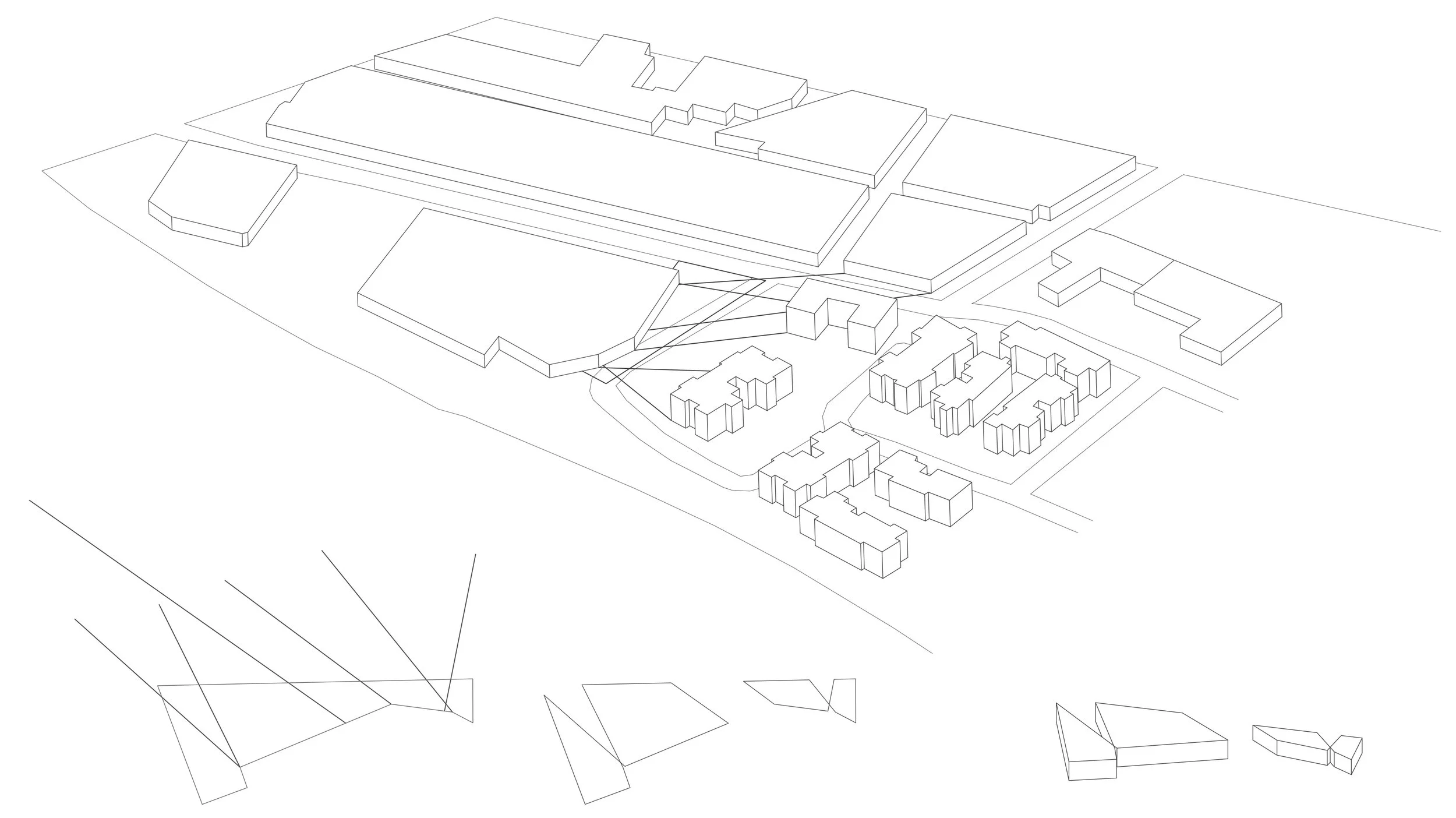
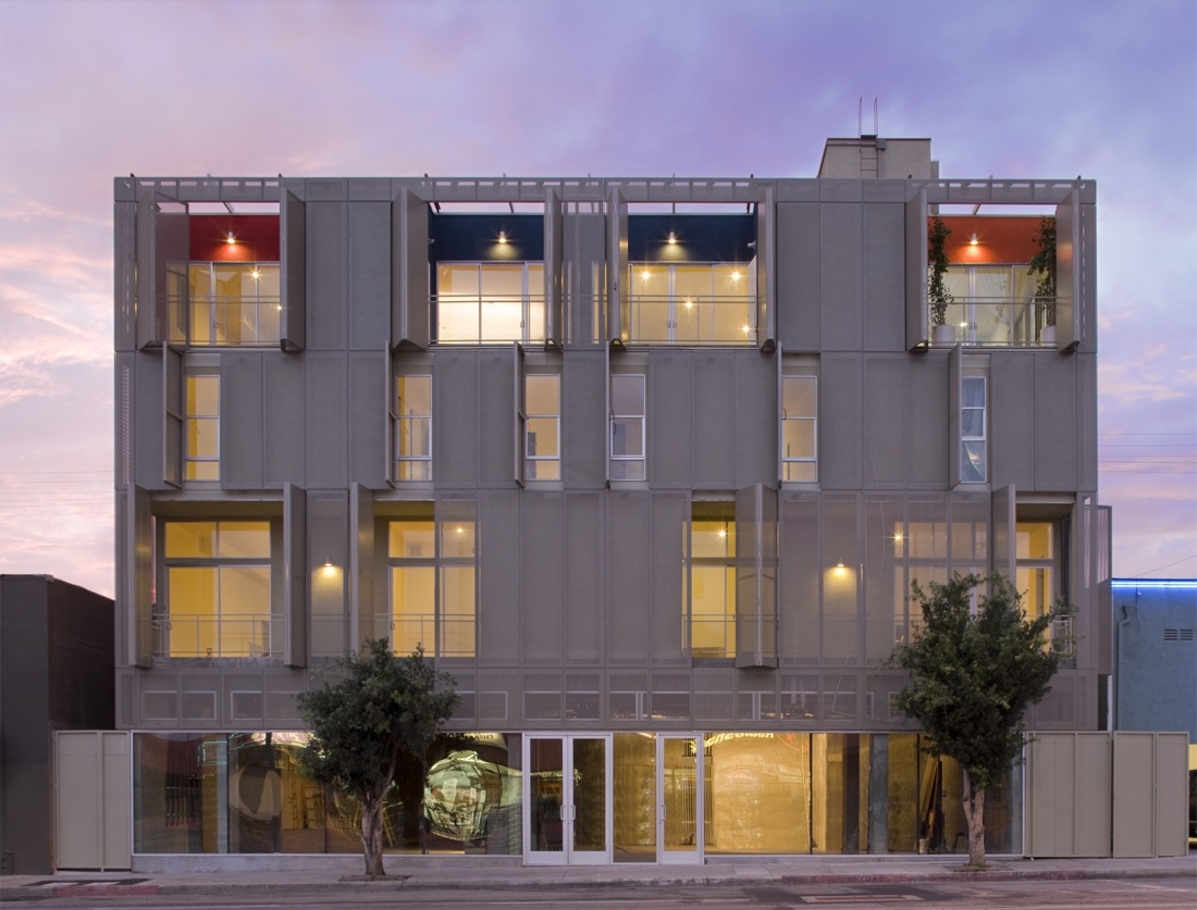
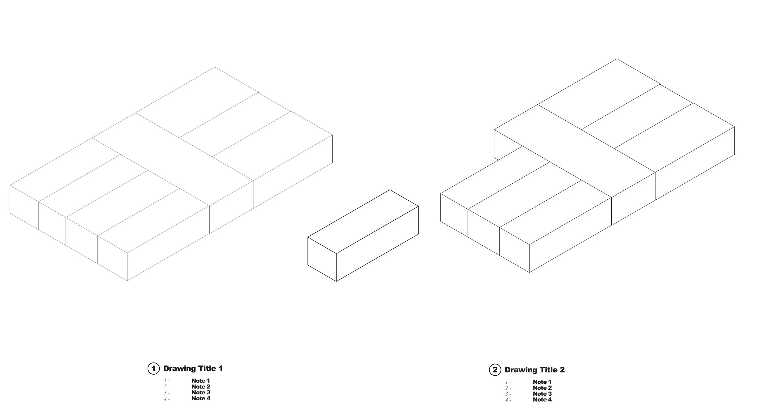
The form of the project becomes greatly influenced by the site it sits on. By considering the site and how it was tucked in an alley. The form tried to occupy the site, and how the space had to layout. In this diagram it shows the mass being divided into three spaces. Two for people to inhabit, and one for the parking space in order to create open areas around the building for people to use.

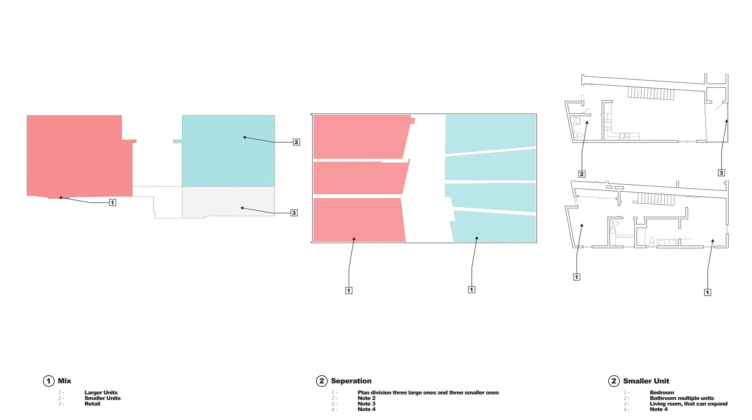
The project evolved into a slab typology, which allowed floor plates to shift creating open areas within the same space from the form below it.
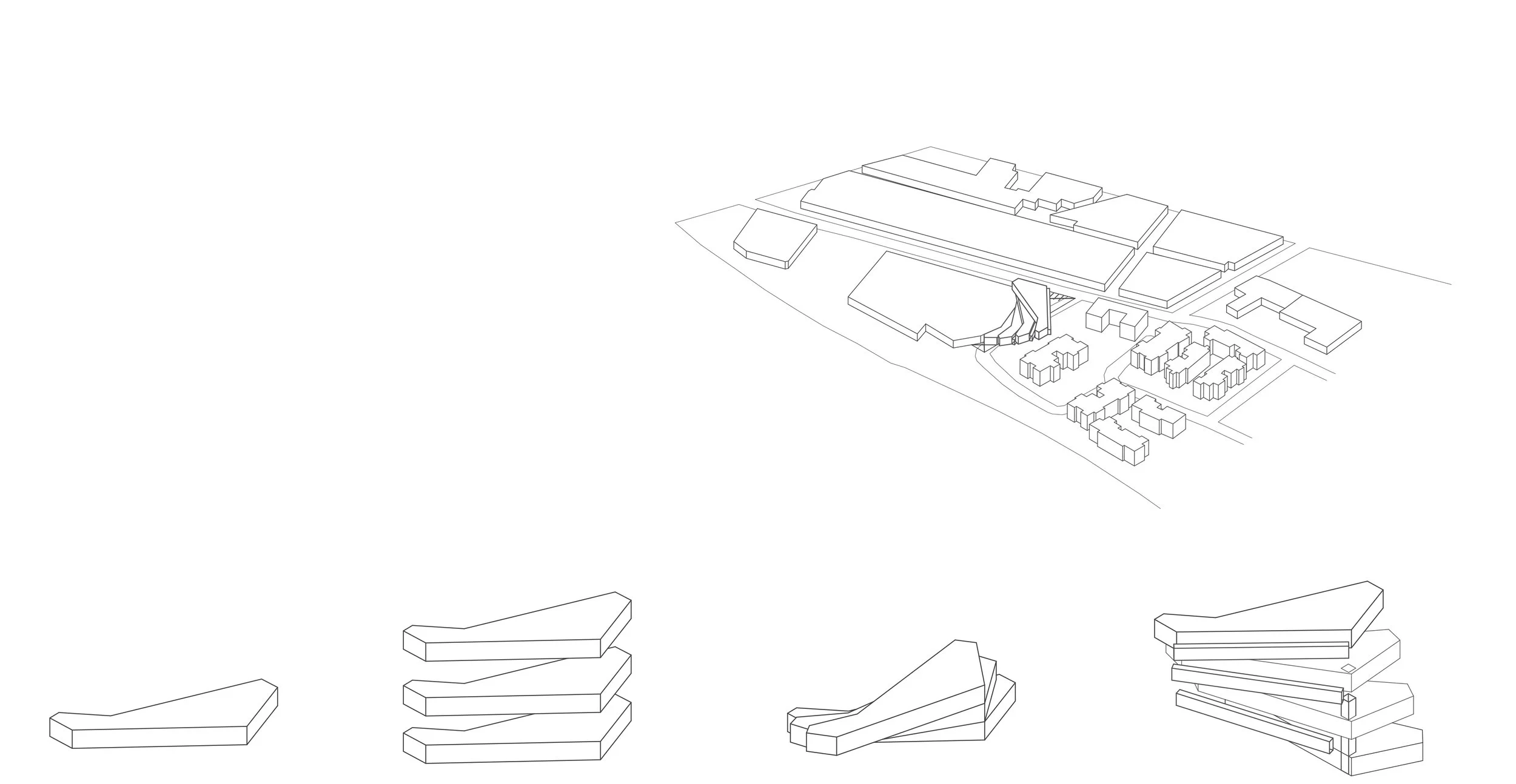

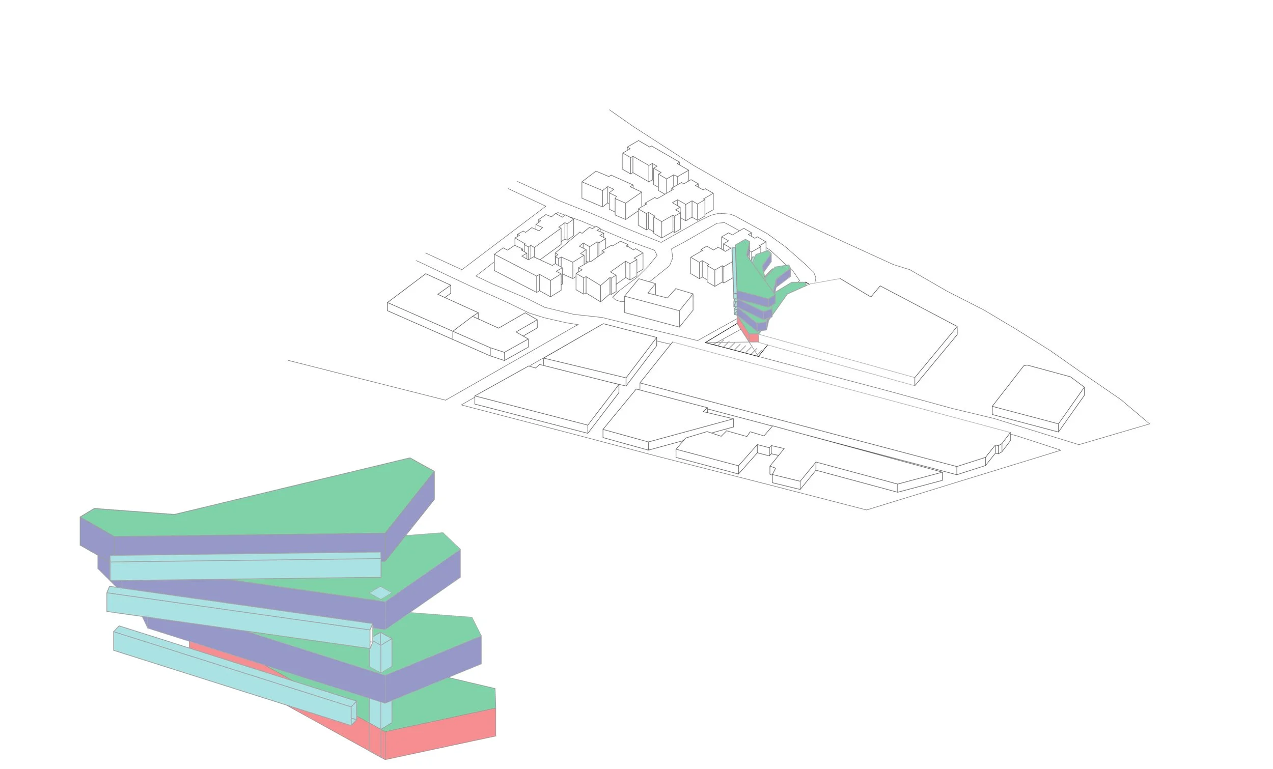
In doing this shift, it enables the mass to fan out and frame different views for the inhabitants towards the city.
As the mass started to fan out, and extend over to the other residential buildings. It started to occupied the aerial space. The project referenced the adjacent building, that was within the same space as the outline. By retaining the indent it created on the site. Since one part of it was all industrial, and the other residential the area for a park was reduced. By producing these shifts in the project in a vertical direction, it started to create open areas for people to use.
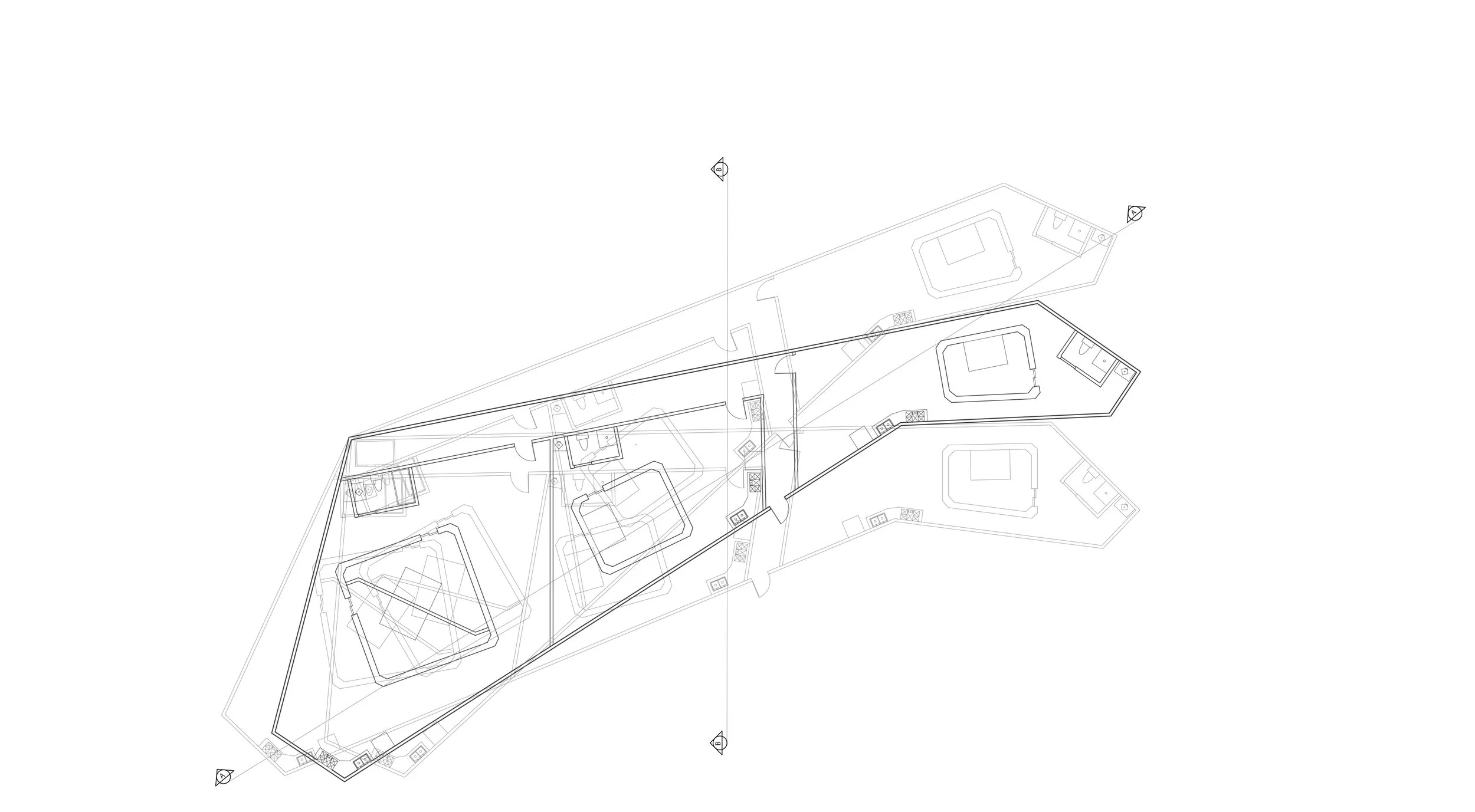
OVERLAY FLOOR PLANS
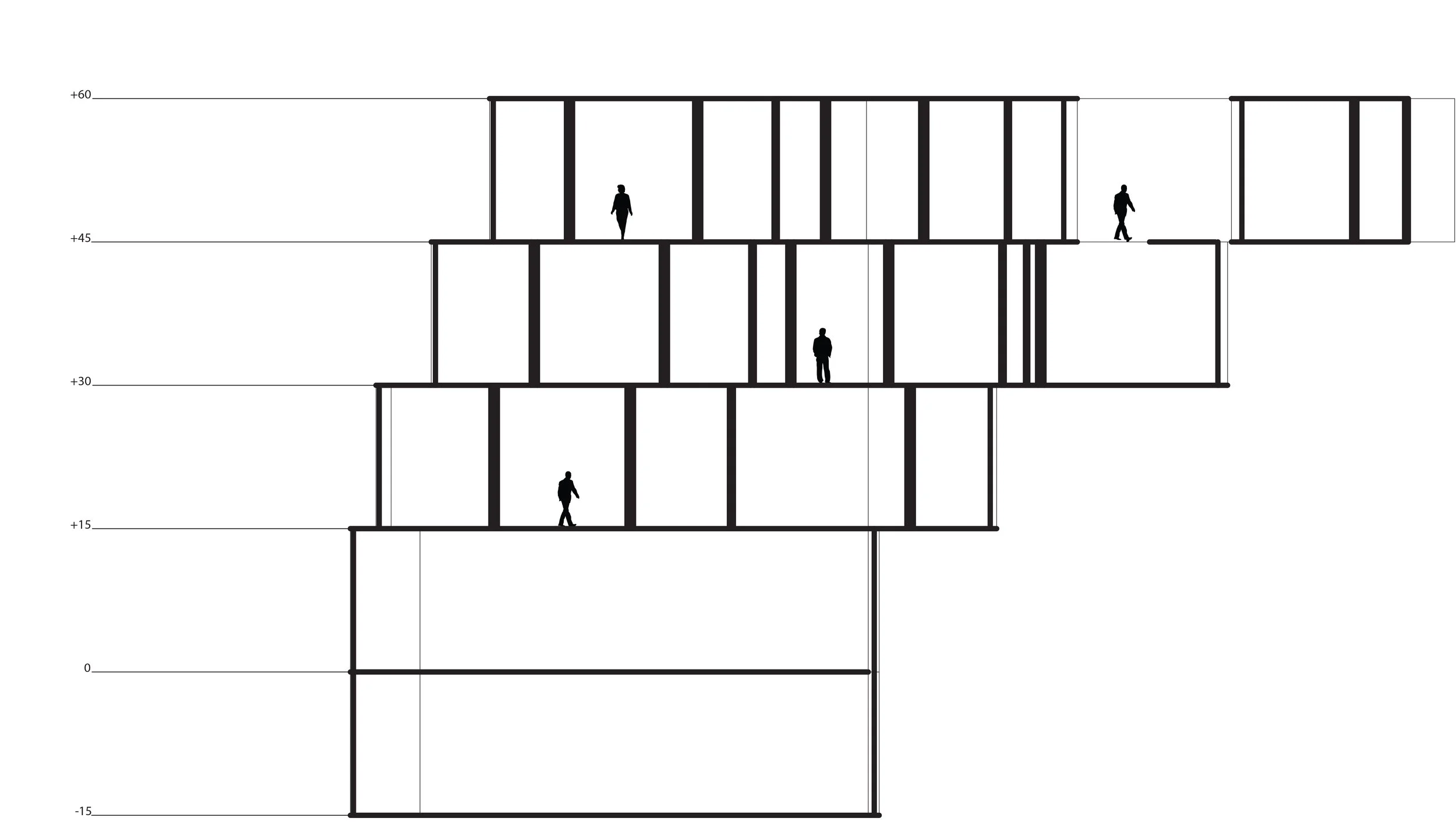
SECTION A
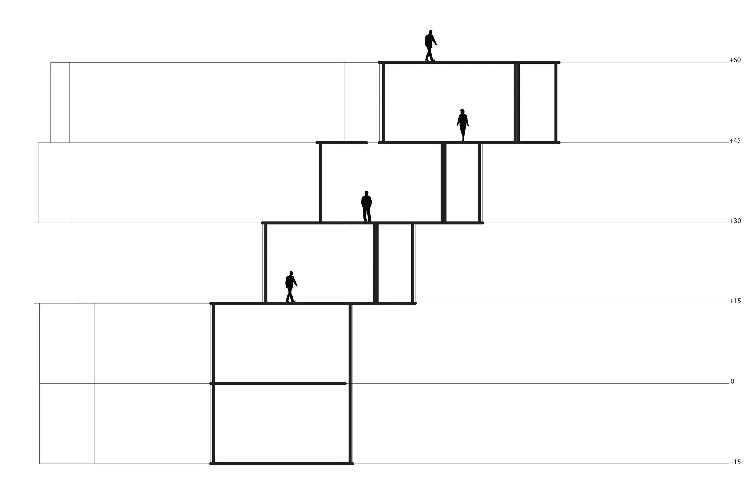
SECTION B
By re-constructing the original mass into a more condense mass it allow the mass to retain the shift. The shift on building allow for an open space that elevates the user from ground level to to roof level of the residential building. Allow for the private and public to intermingle.
SITE PLAN
OVERLAY FLOOR PLANS
The way the floors are laid out, is that there are five units on each floor and they are two stories. The bottom would contain all the main dwelling functions, the second floor was the bedroom. By having the bottom floor longer than the top, it created an open area for the individual or couple to have company. Also to have an outdoor area, which some of the apartments lack. The bottom floor also had a small open area, that extended the space from the living room out into the small courtyard.
SECTION - AA
SECTION - BB
AXONOMETRIC VIEW OF BUILDING IN CONTEXT
PERSPECTIVE VIEW FROM STREET
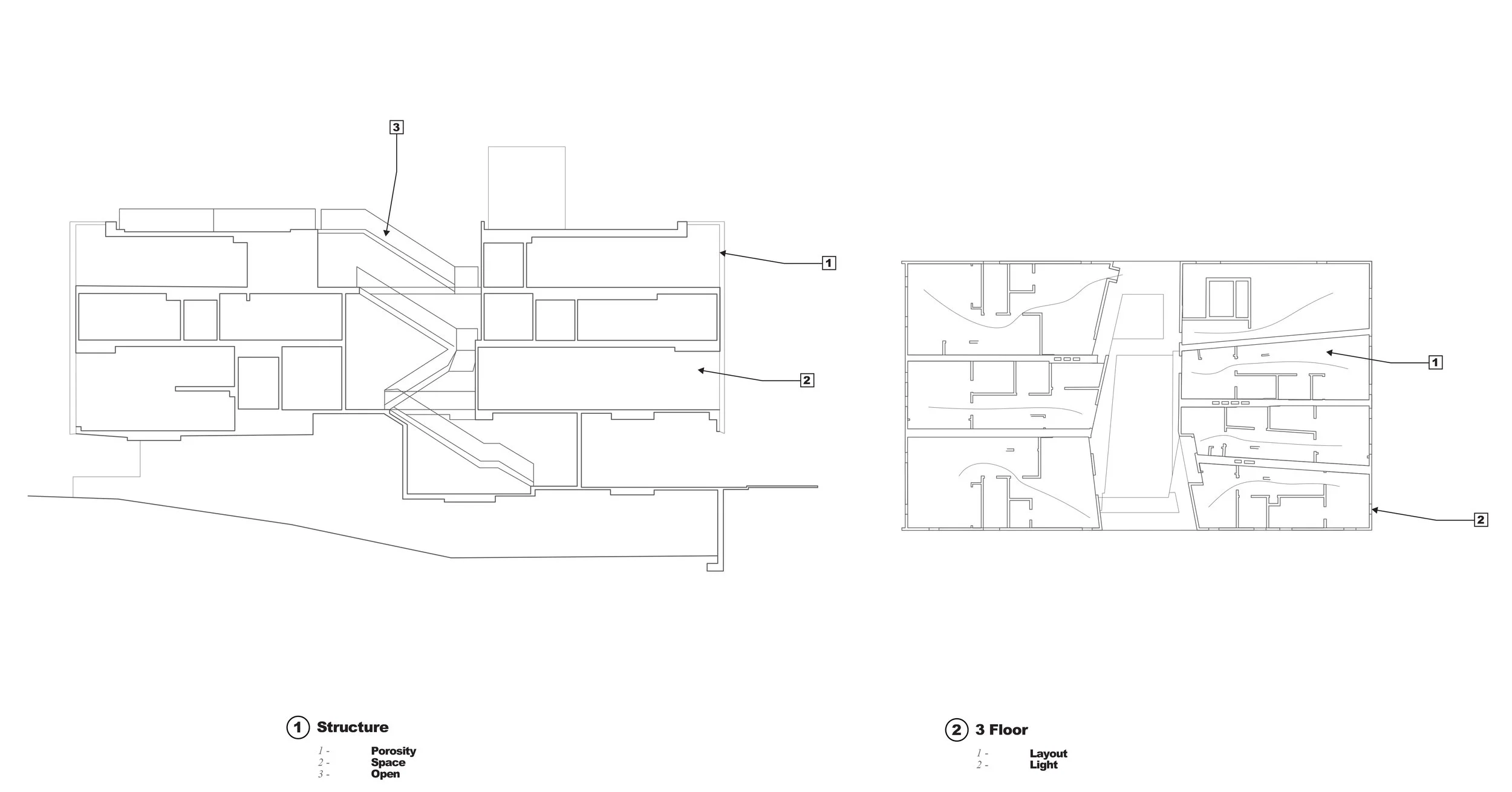
On the other side of the structure, is this pathway that allows anyone to walk up and reach the top of building, where a gathering space can be used. The slow ascending path also allows people to view the city, and slowly discover a new part of it. This open area responds to the lack of public space within the site, by providing one for the residents of the project and the community.
FRONT
BACK
SIDE
The model explores how the sun interacts with the public and private sectors, throughout different times of the day and seasons. By having the shift of each floor plate from one another, it created a shading system. Not only did the shift help create a shading system, but by pushing the second floor back the sun wouldn't reach the bedrooms.
Museum
The project was to design a museum located on site of the 101 south Vermont exit. Starting off with research looking at the MAXXI ( National Museum of the 21st Century Arts) museum design by Zaha Hadid.
Title C.A.R Museum
Instuctor Gerard Smulevich
Location Vermont exit on 101 south
Year 2017
Partner- Ramiro Guerrido
First looking at its site context, and how it related to its form. Noticing that the grid had an influence on the form of the project.
Looking at the floor plans, one feature of the museum layout was striking. The circulation aspect of it, how it not only went in a linear form but also in a vertical one.
The way it used the louver system to deflect the light coming into the space, but still using light in the spaces that needed.
Access Points
Intersections
Visiting the site where the museum would be located, a lot of features appear within the area. First it had a lot of access points, to enter the site from the street above. The access points also created intersections between each other.
Heavy Automotive
City Grid
The position of the site is that is located between the 101 freeway, breaks the city grid at the start and the end of the site. Having this heavy used path with automobiles, the traveling vehicles would outline the landscape.
The study of the sun, in which a large tower mass would cast a shadow onto the city. The sun diagram helping show how the shadow would affect the city.
Tower Mass Model
Tower Mass Model
Linear Mass Model
Linear Mass Model
Starting off with the same concept model, how the mass of the museum might take shape. Exploring from the tall mass to a linear form, permitting to show case the art work. The museum would be showcasing a car collection from a private collector. By defining the collection the project having a more linear form.
Circulation
Top View Circulation
Looking at the circulation, and how people would move within the space. The project refers back to some of the MAXXI circulation, where people would be able to move linearly and vertically. The museum would allow people to view from a high point, and have an overview of the whole museum.
As the process continued the mass shifted, from a heavy to a lighter structure. The structure would produce the apertures, that would allow the sunlight to penetrate and light up spaces. In retaining the aspect of a vertical movement, small floor plates where located at the bottom of the structure.
Model
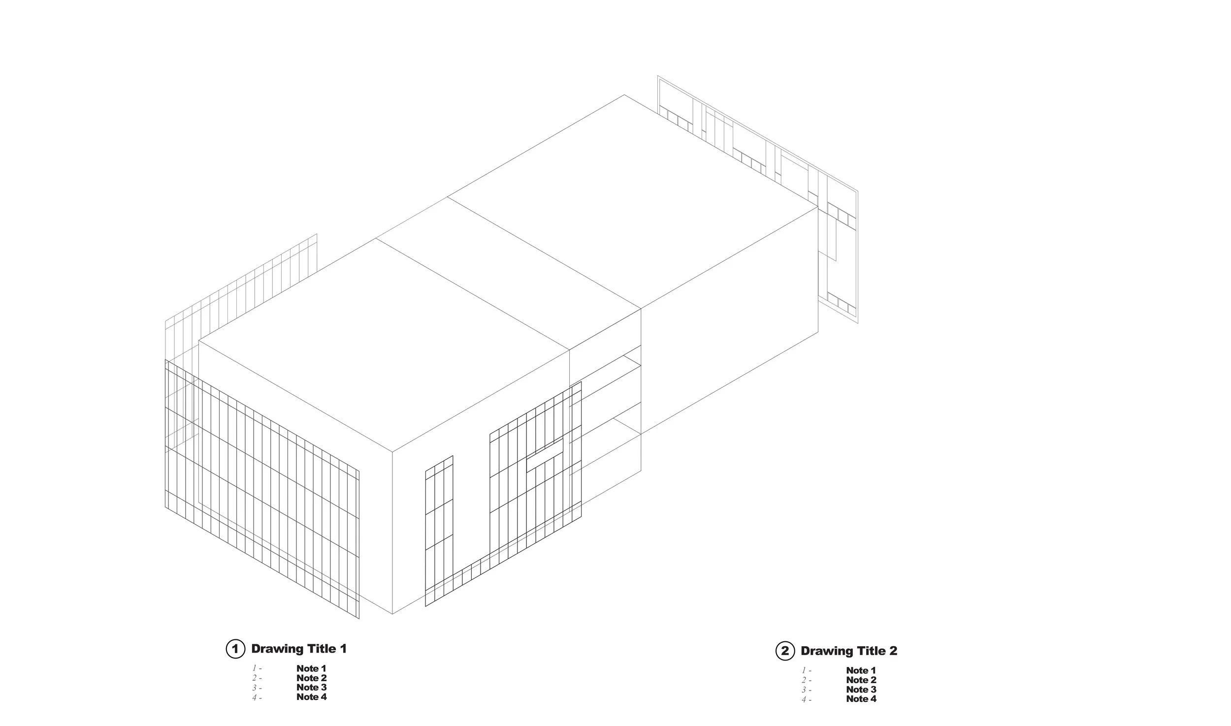
As the project evolved to this point, the structure becomes very important in allowing it to cantilever over Vermont. The way the structure is composed at this point, it would allow the vehicles passing by to view the exhibition.
First Floor Plan
Second Floor Plan
Section
This section shows, the composition of how the cars would be displayed with in space. The tower in the middle not only creates a distortion within the museum, but it also serves as the temporary exhibition where the cars could periodically be changing.
Elevation
As the ideas were being developed, to further improve on the form of the museum. Different iterations manifested, that lead to creating a tower extruding from the linear form. This tower allowed for a different configuration of the space. Displaying the cars to the people who drove by the structure.
The plan of the museum was an open space, where visitors would be able to see all the cars being displayed. Some cars would be placed in the tower where they would change faster, than the ones on display in the main space. The tower serves as a billboard that would show what cars where being displayed.
The renderings display the inside of the museum and its structure. The building has a glass curtain skin, that allows lots of natural light to enter the space.
1
2
3
4
5
Diagram 1 displays how the tower uses the concept of a kick stand for support. Diagram 2 is how the footing of the structure connects to the ground. Diagram 3 shows three things, the use of the space frame to hold up the roof. The louvers that help provide shade from the sun, and the perforated beam that expands through the floor plate. Diagram 5 highlights the truss system that is being used as the main structure of the building.